ECE 5725 Final Project: PlayPi by Sherri Qazi (sq86) and Daniela Makowka (dcm288) 5/16/2024
I: Objective
The objective of our project was to incorporate a motor system that would spin a strip of LED lights, and sync these light effects to the music being played by the RaspberryPi using spotify. However, we decided to make our project more complex by creating a persistence of vision display that would create an image that would sync to music. Initially, we were going to do a heart, but due to time constraints and technical limitations, we opted to do a flower instead. The idea is that the flower petals would sync to the beat of the music, growing or shrinking in size alongside functionality to change the color of the petals.
II: Introduction
For our Embedded OS class, we had four weeks to design and create a project that we would present in front of our professor and the TA's. For our project, we were inspired by Persistence of Vision projects and wanted to implement a persistence of vision project that was interactive with music. It would create an image of a flower that would grow and shrink with the beat of a song that would be played through a speaker system connected to the RaspberryPi. We at first wanted to create an embedded system that involved a display that was interactive with music. We thought of doing an animation on the PiTFT display and having the user choose what song was going to be played. We were planning to do this by having the RaspberryPi connect to the user's phone and through the Spotify app, the user could choose what music would be played from the RaspberryPi to speakers connected to an audiojack. Then, using a microphone, the RaspberryPi would analyze the music/sound being outputted and the animation would react appropriately. However, we thought that was too simple and wanted to add more complex elements to the embedded system. To make it more complicated and create a bigger visual, we added LEDs to the design. We remembered Persistence of Vision projects and came up with the idea to implement a Persistence of Vision project that created an animated LED image that is interactive with the Spotify music. We then created a list of materials we would need, formed a schedule of each task we'd finish each week, and created the project, making a few modifications along the way.
Video Overview:
III: Hardware Design

LEDs
For our LEDs we decided to use the NeoPixel LED strip from AdaFruit. To test that it was able to work with our RaspberryPi and that all the software and wiring was configured correctly, we first tried to turn on one LED on the strip. Then, we created a code that blinked each LED on the strip and went down the LED strip in a loop. Once this worked, we knew that everything was configured correctly and understood how to turn on each LED.
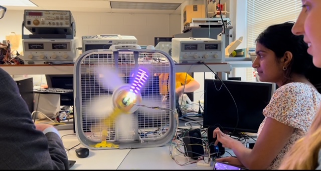
We needed a way to rotate the LEDs really fast. We decided to use a fan to spin the LEDs. At first we were thinking about attaching the LEDs to the fan blades. However, since the fan blades were tilted and couldn'te be drilled, we immediately tried to come up with a new idea. We decided that the best idea would be to drill a wooden plank to the center of the fan that we could mount the LEDs to that would spin as the fan spins. To mount the wooden plank, we drilled a block of wood into the center of the fan. Then, we screwed the wooden plank into the block of wood using several screws to make sure that it was secure. Then, we spun the fan by hand to make sure that nothing was loose or going to fall. Once it was confirmed that everything was secure, we moved onto the next part of our project.
When spinning the LED strip, we realized that there were big gaps between the LEDs on the strip. This may lead to big gaps in the image. To fix this issue, we put a second LED strip right next to the first LED strip and offset it by a bit so that the LEDs from the second LED strip would fill in the gaps. We connected the two strips by soldering wires between the pads at the ends of the LED strips so that the RaspberryPi would recognize the LEDs on LED strip 1 as LEDs 0-12 and the LEDs on LED strip 2 as LEDs 13-25.
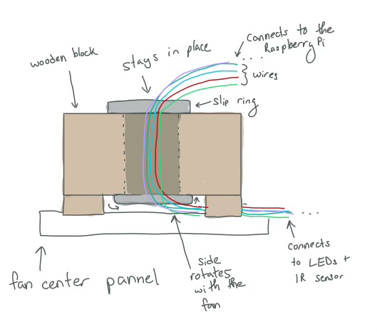
Slip Ring
A first mechanical design challenge we came across was with the wiring with the system. We had decided to use a box fan to spin the LEDs. Since the LEDs would be rotating with the fan, it made wiring very challenging. The breadboard with the RaspberryPi was too bulky and would be too insecure if it was strapped to the center of the fan. However, the LED's needed to be connected to the RaspberryPi as they were spinning. To solve this issue, we used a slip ring. The slip ring works so that one side of slip ring can stay stead as the other side spins. There are wires going through the ring so that one side of the wires could rotate while the other side remains steady.
A hole was drilled into the wooden block at the center of the fan to put the slip ring into. Wooden block was slightly raised so that the wire could be reached from the bottom of the wooden block. The wire from the bottom of the block was then connected to the LED strip that was spinning. The wires from the top of the slip ring were connected to the RapsberryPi. This is shown in the image below.
IR Sensor
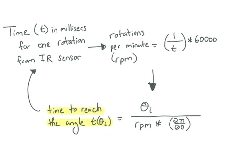
Before the IR Sensor, we tried two different methods to find out when to turn the LEDs on and off: using an IMU and a Hall Effect sensor. Then, we tried using an IMU to get the blade position. However, the software required to calculate the data from the IMU had a hard time keeping up with the speed of the fan. However, we found that we probably could just use the time it takes for the fan to complete one rotation to find out when to turn the lights. This would involve using the time it takes to complete one rotation to calculate the rpm. Using the rpm and the angles the LEDs change, we could then calculate estimeate for the time it takes the fan blades to reach those angles. To calculate this time, we first tried using hall effect sensors. However, we found out after connecting the hall effect sensors and testing them that the hall effect sensor would only detect the magnet when the magnet was really close to the Hall Effect Sensor. When attaching the Hall Effect Sensor to one of the blades of the fan and the magnet to the bottom of the fan, we found that the readings from the Hall Effect sensor were not very accurate.
We then tried using an IR sensor and found that it worked the best. The IR Sensors are connected using the wiring from the slip ring. We had the IR transmitter connected the blade of the fan that was parallel to the wood plank. The receiver was attached to the wooden plank. This way, the transmitter and the receiver are parallel to each other as the fan is rotating. There is a cardboard barrier sticking out from the bottom of the fan. As the IR sensors pass the fan, the receiver will not receive the light signal outputted from the transmitter. Therefore, it will output a 1 everytime the fan blade reaches the bottom of the fan. We turned on the fan and printed the number of rotations and the rpm to test this setup. We compared the rpm with the average rpm of a fan to test the accuracy and precision. We found that the data was pretty accurate and that this system worked the best for us. Using this, we were able to calculate the timings of when to turn the LEDs off and on.
Microphone
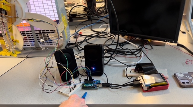
We connected the microphone to the Arduino. The microphone was connected to the ADC GPIO, the 3.3V, and GND pins.
Speakers
Speakers were connected to the RaspberryPi using an audiojack.
IV: Software Design and Testing
RaspberryPi vs. Arduino
We split the flower image into angles and determined which LEDs we turned off and on at certain angles. At first we used the RaspberryPi to do all our angle calculations and LED code. However, we found that the RaspberryPi could not keep up with the speed of the fan. We tried to print statements in our for loop to figure out how slow the RaspberryPi was compared to how fast we needed the RaspberryPi to run our calculations. We measured the elapsed time from the start and end of the while loop we used to update the rpm and do the LED logic. We found that the Raspberry Pi took 0.07 seconds to go through the while loop once. Meanwhile the time to make one rotation was estimated to be 0.05 seconds. This means that the time to get to each angle was less than 0.05 and the RaspberryPi was not fast enough to meet the timing requirements for each of the angles. We came up with the solution to use an Arduino. AdaFruit has a FastNeopixel library only for the Arduino that would help with speed. In addition, the Arduino runs its program in C and was a lot faster than the RaspberryPi. We transferred all our files onto the Arduino and changed it so that everything was in C. This helped with the timing a lot. One difficulty we had, however, was that the Arduino Uno only has 32K bytes of storage meaning we were limited to the amount of storage we could use. Had we known about the limited storage capacity of the Arduino Uno, we would have used the ESP 32 microcontroller like some other groups did which has Mega bytes of storage. We found the limited storage difficult when we were mapping the LED;s using a 3 dimensional array. The 3 dimensional array took up too much storage. We tried playing around with 2 dimensional arrays and narrowing down the amount of angles we used to reduce the size of the array. However, with the limited storage, the Arduino stil struggled with iterating over that large of an array. Therefore, we decided to use a simple flower image that required 5 angles and created if statements to keep track of the timing and the actions of the LEDs.
Angle calculations
To estimate the time it took the fan blade to get to a certain angle, we used the rotations per minute. The rotations per minute was calculated using the information for the light sensor. The light sensor functioned inside an interrupt service routine. Everytime the GPIO attached to the lightsensor was detected to be high, an interrupt would run that would update the elapsed time since the last interrupt and the elapsed time would be used to find the time it took the fan to make a full rotation. Then this time would be used to calculate the rotations per minute using unit conversions. Very occassionally, the light sensor would be incorrect and detect the cardboard at the bottom twice. This led to a faster rpm. To avoid incorrect data, we added an if statement that made sure the rpm was never changed if the calculated rpm was higher than 600 (we saw that the fan on average had an rpm of 428 at the lowest setting). This rpm would be used to calculate the time used to get to the 5 angle values of the flower petals. This logic can be seen below.
In a while loop, we kept checking the current time with the estimated time it takes to reach each of the flower petal angles. If that time was reached, then the LEDs would turn on for a certain amount of time and then turn off once that time has passed. This gave the illusion of a flower petal as the fan was spinning. While the code was going through the while loop, the rpm and angles were constantly being updated by the interrupt code.
Audio Sampling
Audio was sampled every 50 milliseconds using a microphone. A while loop inside the loop() function was used to measure 50 milliseconds. Over the time of 50 milliseconds, the code reads the analog input from the microphone and keeps track of the minimum and maximum data over the course of the 50 milliseconds to get the peak to peak amplitudes. After 50 milliseconds, the peak-to-peak amplitudes are used to determine the size of the flower (as in how many LEDs to turn on and what size to make the flower). We created 4 states: one state where the flower petal was only 3 LEDs long, one state where it was 9 LEDs long, one where it was 15 LEDs long, and the last one where it was 21 LEDs long (5 LEDS in the center were always yellow to represent the center of the flower). The logic for comparing the current time to the calculated angle time was put into the 50 millisecond while loop to make sure that the time was always being compared to the calculated angle time. If the time was calculated to be about the calculated angle time, then the code would check the state to turn on the appropriate number of LEDs for the flower petals. This created the illusion of the flower pedals updating in realtime with how loud the music was. It was interesting getting to interact with the system. For example, if you yelled into the microphone the flower would get bigger. This was a good way for us to test the system. Since the flower pedals' lengths were updating in realtime, the length of one pedal could be different than the length of another pedal if there was a sound difference by the time the blade made it to the next angle. This added an interesting more realtime affect as the flower was updating fast in realtime with realtime sound.
SpotifyD
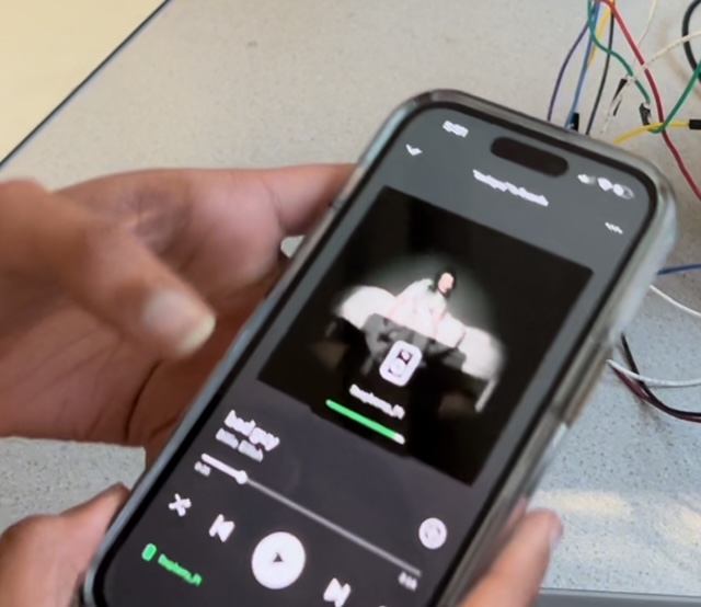
For integrating Spotify with the Raspberry Pi we used the SpotifyD library that uses ALSA’s (Advanced Linux Sound Architecture) backend to output the sound to our speakers. Our steps included downloading a tar file from https://github.com/Spotifyd/spotifyd/releases to our current directory depending on which ARM we were using (ARM7l in our case). Next, we unzipped the tar in our current directory, and checked if we had Spotifyd in our library. Finally, we created a spotifyd.conf file which essentially configured the settings on how Spotify will connect with the Raspberry Pi. We also changed the device variable to “hw” since that represents using the audio jack for audio output. The connect device was our Raspberry Pi, and the idea is that the Raspberry Pi acts as a bluetooth speaker for the Spotify app on our phones. Below is an example of what we did to our conf file:
  [global]
  username = “Private Information”
  password = “Private Information”
  backend = “alsa”
  device = “hw”
  mixer = “PCM”
  device_name = “Raspberry Pi”
  bitrate = 96
  cache_path = “cache_directory”
  volume-normlisation = true
  normalisation-pregain = -10
For testing, we ran the command ./spotifyd --no-daemon in our current directory, and simply connected my phone to the Spotifyd. Overall, we did not have issues with this step, and we played a couple songs with the speaker. If we did have issues, we would debug by trying restarting the command and it would usually work.
Serial Communication Between Arduino and Raspberry Pi
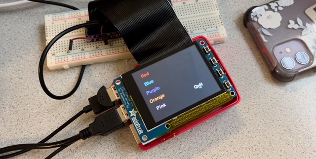
The idea of this project is to have the user have fun and integrate themselves into the light show experience. Therefore, we decided to give them an option to switch between different color options (Red, Blue, Purple, Orange, Pink) for the flower petals using the piTFT. Therefore, we needed the Raspberry Pi to communicate with the Arduino.
Raspberry Pi Side
To make the process easier, we decided to send string versions of numbers representing the different colors over serial. For example, Red is 1, Blue is 2, Purple is 3, Orange is 4, and Pink is 5. To change between the colors, we would have a global variable called sendcolor which would change depending if the user pressed the particular color (or area on the screen) on the PiTFT. We displayed the colors on the piTFT by using text of the color and coloring it the same color (i.e. the word Purple being colored Purple). We contained the colors in a color dictionary, and used a for loop that looped through the dictionary that used blit to display them on the screen. We established a serial connection using the function serial.Serial('/dev/ttyACM0', 57600, timeout=1) in which ACM0 represented the Arduino. In order to write the string with a newline appended to it and send it over to the Arduino, we used the write function and encoded the string in a ‘utf-8’ format (to send information in bytes). For debugging purposes, we used the function readline().decode(‘utf-8’).rstrip() to see what strings the arduino was receiving.
Arduino Side
Reading the bytes on the Arduino side was relatively simple. All we had to do was check if Serial was available, and if it was, use the functionSerial.readStringUntil('\n'), and convert the string to an int using receivedString.toInt() to save into a global variable numstr. Again, we represented the colors as int numbers with the same numbering before the difference being we are working with ints. We decided to compare with ints since it’s easier C. Then, using for loops to compare numstr to the int representation of the colors, we set the three global variables (RGB) to a particular RGB value to create that color depending on if the statement was true. For example, to create purple we did
  if (numstr == purple)
  {
    COLOR_R = 148;
    COLOR_G = 0;
    COLOR_B = 211;
  }
To test our code, we ran on the code on the Arduino and connected it to the raspberry pi to make sure that the correct values were sent. Once we confirmed that, we tried testing on the LED strips, but the color changes would last for a second. After changing the logic for the if statements, we realized we needed to use else-ifs because after the second loop iteration from changing the color, the loop would always end up with the color with else statement. Thus, we decided to change all the ifs to else-ifs except the first one.
V: Results
Since this was our first time working with a hardware heavy project and going in not knowing how persistence of vision displays work, this project had many ups and downs. At the start, we worked on connecting the Raspberry Pi to our phones via bluetooth. Luckily, there was a lot of documentation, but many repositories for libraries were not updated. We struggled to find something that worked for us until we found spotifyd. The other issues we had was configuring our microphone with PyAudio which we ended up not using due to spotifyd using Alsa which uses the same sound architecture as PyAudio. We learned that we had to go into the alsa.conf to change the sound card to support our microphone. Then, when calculating the angles we struggled using the hall effect sensor to calculate the rotations per minute since the magnet was not strong enough. As a result, we tried the IMU 6050, but the fan was spinning too fast for the IMU to collect accurate data. Finally, after trying for 2 weeks, we settled on an IR beam break sensor which worked as intended and helped us get accurate angle data. Even after getting the angle calculations to work, we realized that the Raspberry Pi was running very slow through our while loop which caused the LED lights to not be updated in time. For that reason we decided to switch to an arduino uno that can run C++ code which runs much faster than python. Below shows a table comparing the loop times between Arduino and Raspberry Pi. Once we got the code to run the arduino, we still couldn’t get the heart image we tried hard for. Overall, a lot of our components did not work initially, but our partner and I were able to compromise some of our initial ideas to get a viable product working/ Although we were not able to get the heart image we wanted, we still were able to create a flower that was able to sync with the music. We were able to complete our objectives of 1) sync these light effects to the music being played by the RaspberryPi 2) using spotify to control the music 3) creating an image with the LED lights, but not the complexity of our liking.
| Arduino | Raspberry Pi | |
| Timing in Main Loop | 50 milliseconds | 400 milliseconds |
Conclusion
Conclusion
Through this project, we were apple to accomplish a lot. One thing we were able to accomplis was connecting the RaspberryPi to Spotify on a user's phone. This required a lot of research and testing different methods we found online. The second accomplishment we made was creating a Persistence of Vision project where an image of a flower was displayed. It wasn't noisy and a viewer could tell that the image on the fan was a flower. Another task that we accomplished was animating the flower. The flower shrunk and grew. Lastly, we accomplished having the image of the flower be reactive towards sound. The flower shrunk when there wasn't much sound and grew when sound became very loud. It was responsive to the loudness of the environment.
One thing we discovered that definitely did not work was using the RaspberryPi in the language Python to do any really fast calculations. C was a lot faster than Python. Also, iterating over large data sets with devices that had limited storage was something that doesn't work. If you have big arrays or something that requires a lot of storage, make sure that the device you are using can handle that storage or that you have an external large storage system.
We learned a lot from this lab. There were many trial and errors before we go the final project working. For example, we learned about how fast C is compared to Python. The LEDs were able to work a lot faster when we were using C. Additionally, we learned about hardware and software debugging. It was really helpful during the lab to test each part of the lab individually before putting lal the pieces and componenets together. Our lab has a lot of pieces and components. Therefore, debugging was sometimes a struggle. However, by testing individual parts, we were often able to narrow down bugs and issues to specific systems which were really helpful.
Another thing we learned was to read into the datasheet of the supplies you are using. We should have read more about the Arduino Uno before deciding to use it in our project. Then we would've known about the storage and avoided some issues. Overall, we enjoyed the project. It was an insightful project and neat to create an interactive image using rotating LEDs.
VI: Contributions

Daniela helped assemble all the hardware together. All the wiring configurations and mountings were done by Daniela. Also, the configuraiton of the fan with the block at the center of the fan with the plank sticking out of it and the slip ring inside the wooden block. She also worked with Sherri to figure out the code for turning the LEDs on and off at the correct times to create the Persistence of Vision image using the fan. She worked on implementing code first on the RaspberryPi and transferring that over to the Arduino. Both Sherri and Daniela worked on debugging this code. Then, Daniela worked on adding the microphone to the system and created the code that analyzed the sound from the microphone. She also helped with serial debugging. Lastly, Daniela did half of the lab report and Sherri did the other half. Sherri focused on getting the UART connection between the Arduino and Raspberry Pi to work as well as displaying the colors on the piTFT and the logic for that. Sherri also contributed in setting up the IR sensor as well as displaying the flower shape itself. Sherri set up the bluetooth connection between the spotify and the Raspberry Pi with Daniela.
For the lab report, Daniela worked on the introduction, design for the hardware and fan logic, the conclusion, references, code formatting, drawings and contribution sections. Sherri worked on making the video, the objective, design for spotifyd and serial, results, budget, commenting and formatting code, and the contribution sections of the lab report.
VII: Future Work
If we had more time to work on the project, Daniela and I would have focused on creating more complicated images for the persistence of vision display such as heart, star, or bitmapped images of photos. In addition, having functionality to switch between images for the user to select.
Budget
| Part | Cost | Source |
|---|---|---|
| IR Beam Sensor | $5.95 | Provided in Lab |
| Microphone MAX 4466 | $6.95 | Provided in Lab |
| Fan | $20.00 | Provided in Lab |
| NeoPixel LEDs | $10.00 | Provided in Lab |
| Speakers | $20.00 | Provided in Lab |
| PiTFT | $44.95 | Provided in Lab |
| Raspberry Pi 4 | $35.00 | Provided in Lab |
| Miscellaneous (Wood, Wires, etc.) | $5.00 | Provided in Lab |
VIII: References
- Adafruit NeoPixel
- SpotifyD Installation Guide
- MAX 4466 Datasheet
- IR Beam Datasheet
- SP2024 Lecture Note 17
IX: Code Appendix
Arduino Code
  #include
    #define NUM_LEDS 28
    #define PI 3.1415926535897932384626433832795
    CRGB leds[NUM_LEDS];  // FastLED library data structure


    // Time variables:
    float rpm = 0;                 // Rotations per minute of the fan
    int num_spins = 0;             // Number of fan spins
    float curr_theta = 0;          // Theta (used for testing one theta)
    long start_time = millis();    // Start time of the rotation (used to calculate the elapsed time of the rotation)


    // Angles:
    float theta = 0.2;             // Angle of first petal
    float theta1 = 1.456;          // Angle of second petal
    float theta2 = 2.712;          // Angle of third petal
    float theta3 = 3.968;          // Angle of fourth petal
    float theta4 = 5.224;          // Angle of fifth petal


    // Time to get to each angle:
    float theta_time = 0.0;
    float theta_time1 = 0.0;
    float theta_time2 = 0.0;
    float theta_time3 = 0.0;
    float theta_time4 = 0.0;


    // Time to collect microphone data
    const int sampleWindow = 50; // Sample window width in mS (50 mS = 20Hz)
    unsigned int sample;


    /**
    There are 4 states for the length of the flower petals:
      state = 0: 3 LEDS
      state = 1: 9 LEDS
      state = 2: 15 LEDS
      state = 3: 21 LEDS
    **/
    //COLORS
    int COLOR_R = 148;
    int COLOR_G = 0;
    int COLOR_B = 211;


    // Color states:
    int red = 1;
    int orange = 4;
    int blue = 2;
    int purple = 3;
    int pink = 5;


    int numstr=3;
    int state = 0; // goes up to 3 for the different color states
    int ordered_leds[NUM_LEDS];


    // Setting up the Arduino
    void setup() {
      String receivedString;
      // put your setup code here, to run once:
      FastLED.addLeds(leds, NUM_LEDS);  // setup the led strip using fast-led lib
      Serial.begin(57600); // Serial setup

      // IR Sensor interrupt (pin 2)
      pinMode(2, INPUT_PULLUP);
      attachInterrupt(digitalPinToInterrupt(2), rpm_calc, RISING);

      //Reorder the LEDs so that the higher the number, the farther away the LED is
      int x = 0;
      for (int i = 0; i 0) {
            // Read the received string
            String receivedString = Serial.readStringUntil('\n');
            numstr = receivedString.toInt();
          }

         // Change LEDs to red if red was sent
        if (numstr == red)
            {
              COLOR_R = 255;
              COLOR_G = 0;
              COLOR_B = 0;
            }
        // Change LEDs to orange if orange was sent
        else if (numstr == orange)
            {
              COLOR_R = 255;
              COLOR_G = 104;
              COLOR_B = 31;
            }
        // Change LEDs to purple if purple was sent
        else if (numstr == purple)
            {
              COLOR_R = 148;
              COLOR_G = 0;
              COLOR_B = 211;
            }
        // Change LEDs to pink if pink was sent
        else if (numstr == pink)
            {
              COLOR_R = 255;
              COLOR_G = 7;
              COLOR_B = 7;
            }
        // Change LEDs to blue if blue was sent
        else if (numstr == blue)
            {
              COLOR_R = 0;
              COLOR_G = 191;
              COLOR_B = 255;
            }

        // Sampling sound from microphone for 50 milliseconds:
       unsigned long startMillis= millis();  // Start of sample window
       unsigned int peakToPeak = 0;   // peak-to-peak level
       unsigned int signalMax = 0;
       unsigned int signalMin = 1024;
       // collect data for 50 mS
       while (millis() - startMillis < sampleWindow)
       {
          //updating angle times:
          theta_time =  theta/(rpm*((2*PI)/60));
          theta_time1 =  theta1/(rpm*((2*PI)/60));
          theta_time2 =  theta2/(rpm*((2*PI)/60));
          theta_time3 =  theta3/(rpm*((2*PI)/60));
          theta_time4 =  theta4/(rpm*((2*PI)/60));


          //Read microphone data:
          sample = analogRead(0);
          if (sample < 1024)  // toss out spurious readings
          {
             if (sample > signalMax)
             {
                signalMax = sample;  // save just the max levels
             }
             else if (sample < signalMin)
             {
                signalMin = sample;  // save just the min levels
             }
          }
          comp_angle(); // update flower
       }
       peakToPeak = signalMax - signalMin;  // max - min = peak-peak amplitude
       double volts = (peakToPeak * 5.0) / 1024;  // convert to volts

       // Change petal length based on the amplitude from the microphone
       if (peakToPeak <=20){
        state = 0;
       }
       else if(peakToPeak <=50){
        state = 1;
       }
       else if(peakToPeak <= 100){
        state =2;
       }
       else{
        state =3;
       }
    }


    // Calculates the rotations per minute and updates it
    void rpm_calc() {
      num_spins ++;
      float tot_elapse =  millis() - start_time;
      float temp = (1/tot_elapse)*60000;
      // Change the rpm only if the rpm data makes sense (anythin above 600 is too big and is an error)
      if (temp <600){
        rpm = temp;
      }
      // reset start time to be when fan starts second rotation
      start_time = millis();
      curr_theta = 0;
    }
    void comp_angle(){
      // how much time elapsed since the last interrupt/ since the fan blade was at angle 0.
      float elapsed = millis() - start_time;


      // Check the time and then check the state to see if LEDs need to be turned on and if so, how many LEDS:
      if (elapsed <= theta_time*1000 + 6 && elapsed >= theta_time*1000 - 6){
        for (int i = 0; i < 5; i++)
        {
          leds[ordered_leds[i]] = CRGB::Yellow;
        }
        for (int i = 5; i < 9; i++)
        {
          leds[ordered_leds[i]].red = COLOR_R;
          leds[ordered_leds[i]].green = COLOR_G;
          leds[ordered_leds[i]].blue = COLOR_B;
        }
        if(state==1||state==2||state==3){
          for (int i = 9; i < 15; i++)
          {
            leds[ordered_leds[i]].red = COLOR_R;
            leds[ordered_leds[i]].green = COLOR_G;
            leds[ordered_leds[i]].blue = COLOR_B;
          }
        }
        if(state==2||state==3){
          for (int i = 15; i < 21; i++)
          {
            leds[ordered_leds[i]].red = COLOR_R;
            leds[ordered_leds[i]].green = COLOR_G;
            leds[ordered_leds[i]].blue = COLOR_B;
          }
        }
        if(state==3){
          for (int i = 21; i < 26; i++)
          {
            leds[ordered_leds[i]].red = COLOR_R;
            leds[ordered_leds[i]].green = COLOR_G;
            leds[ordered_leds[i]].blue = COLOR_B;
          }
        }
        FastLED.show();
      }
      else if (elapsed <= theta_time1*1000 + 6 && elapsed >= theta_time1*1000 - 6){
        for (int i = 0; i < 5; i++)
        {
          leds[ordered_leds[i]] = CRGB::Yellow;
        }
        for (int i = 5; i < 9; i++)
        {
          leds[ordered_leds[i]].red = COLOR_R;
          leds[ordered_leds[i]].green = COLOR_G;
          leds[ordered_leds[i]].blue = COLOR_B;
        }
        if(state==1||state==2||state==3){
          for (int i = 9; i < 15; i++)
          {
            leds[ordered_leds[i]].red = COLOR_R;
            leds[ordered_leds[i]].green = COLOR_G;
            leds[ordered_leds[i]].blue = COLOR_B;
          }
        }
        if(state==2||state==3){
          for (int i = 15; i < 21; i++)
          {
            leds[ordered_leds[i]].red = COLOR_R;
            leds[ordered_leds[i]].green = COLOR_G;
            leds[ordered_leds[i]].blue = COLOR_B;
          }
        }
        if(state==3){
          for (int i = 21; i < 26; i++)
          {
            leds[ordered_leds[i]].red = COLOR_R;
            leds[ordered_leds[i]].green = COLOR_G;
            leds[ordered_leds[i]].blue = COLOR_B;
          }
        }
        FastLED.show();
      }
      else if (elapsed <= theta_time2*1000 + 6 && elapsed >= theta_time2*1000 - 6){
        for (int i = 0; i < 5; i++)
        {
          leds[ordered_leds[i]] = CRGB::Yellow;
        }
        for (int i = 5; i < 9; i++)
        {
          leds[ordered_leds[i]].red = COLOR_R;
          leds[ordered_leds[i]].green = COLOR_G;
          leds[ordered_leds[i]].blue = COLOR_B;
        }
        if(state==1||state==2||state==3){
          for (int i = 9; i < 15; i++)
          {
            leds[ordered_leds[i]].red = COLOR_R;
            leds[ordered_leds[i]].green = COLOR_G;
            leds[ordered_leds[i]].blue = COLOR_B;
          }
        }
        if(state==2||state==3){
          for (int i = 15; i < 21; i++)
          {
            leds[ordered_leds[i]].red = COLOR_R;
            leds[ordered_leds[i]].green = COLOR_G;
            leds[ordered_leds[i]].blue = COLOR_B;
          }
        }
        if(state==3){
          for (int i = 21; i < 26; i++)
          {
            leds[ordered_leds[i]].red = COLOR_R;
            leds[ordered_leds[i]].green = COLOR_G;
            leds[ordered_leds[i]].blue = COLOR_B;
          }
        }
        FastLED.show();
      }
      else if (elapsed <= theta_time3*1000 + 6 && elapsed >= theta_time3*1000 - 6){
        for (int i = 0; i < 5; i++)
        {
          leds[ordered_leds[i]] = CRGB::Yellow;
        }
        for (int i = 5; i < 9; i++)
        {
          leds[ordered_leds[i]].red = COLOR_R;
          leds[ordered_leds[i]].green = COLOR_G;
          leds[ordered_leds[i]].blue = COLOR_B;
        }
        if(state==1||state==2||state==3){
          for (int i = 9; i < 15; i++)
          {
            leds[ordered_leds[i]].red = COLOR_R;
            leds[ordered_leds[i]].green = COLOR_G;
            leds[ordered_leds[i]].blue = COLOR_B;
          }
        }
        if(state==2||state==3){
          for (int i = 15; i < 21; i++)
          {
           leds[ordered_leds[i]].red = COLOR_R;
            leds[ordered_leds[i]].green = COLOR_G;
            leds[ordered_leds[i]].blue = COLOR_B;
          }
        }
        if(state==3){
          for (int i = 21; i < 26; i++)
          {
            leds[ordered_leds[i]].red = COLOR_R;
            leds[ordered_leds[i]].green = COLOR_G;
            leds[ordered_leds[i]].blue = COLOR_B;
          }
        }
        FastLED.show();
      }
      else if (elapsed <= theta_time4*1000 + 6 && elapsed >= theta_time4*1000 - 6){
        for (int i = 0; i < 5; i++)
        {
        leds[ordered_leds[i]] = CRGB::Yellow;
        }
        for (int i = 5; i < 9; i++)
        {
          leds[ordered_leds[i]].red = COLOR_R;
          leds[ordered_leds[i]].green = COLOR_G;
          leds[ordered_leds[i]].blue = COLOR_B;
        }
        if(state==1||state==2||state==3){
          for (int i = 9; i < 15; i++)
          {
            leds[ordered_leds[i]].red = COLOR_R;
            leds[ordered_leds[i]].green = COLOR_G;
            leds[ordered_leds[i]].blue = COLOR_B;
          }
        }
        if(state==2||state==3){
          for (int i = 15; i < 21; i++)
          {
            leds[ordered_leds[i]].red = COLOR_R;
            leds[ordered_leds[i]].green = COLOR_G;
            leds[ordered_leds[i]].blue = COLOR_B;
          }
        }
        if(state==3){
          for (int i = 21; i < 26; i++)
          {
            leds[ordered_leds[i]].red = COLOR_R;
            leds[ordered_leds[i]].green = COLOR_G;
            leds[ordered_leds[i]].blue = COLOR_B;
          }
        }
        FastLED.show();
      }
      else {
      for (int i = 5; i < 28; i++)
        {
          leds[ordered_leds[i]]  = CRGB::Black;
        }
        FastLED.show();
      }
    }
Raspberry-Pi Code
  import pygame,pigame
  from pygame.locals import *
  import os, time
  import RPi.GPIO as GPIO
  from time import sleep
  import subprocess
  import serial
  import time
  #Colours
  GPIO.setmode(GPIO.BCM)
  #GPIO setup for Quit Button
  GPIO.setup(27, GPIO.IN, pull_up_down=GPIO.PUD_UP)


  sendcolor = "4" #number that is sent as string over UART to change color of flower petals (4 -> orange)
  def GPIO27_callback(channel): #Quit Button for PiTFT display
      global code_run
      code_run = False


  time_limit = 30
  starttime = time.time()
  code_run = True


  GPIO.add_event_detect(27, GPIO.FALLING, callback=GPIO27_callback, bouncetime=300)
  #Colors
  WHITE = (255,255,255)
  RED = (255,0,0)
  BLUE = (0, 191,255)
  PURPLE = (148,0,211)
  ORANGE = (255, 104, 31)
  PINK =  (255, 105, 180)


  #Environmental Variables for Displaying on PiTFT
  os.putenv('SDL_VIDEODRV','fbcon')
  os.putenv('SDL_FBDEV', '/dev/fb1')
  os.putenv('SDL_MOUSEDRV','dummy')
  os.putenv('SDL_MOUSEDEV','/dev/null')
  os.putenv('DISPLAY','')


  pygame.init()
  pitft = pigame.PiTft()
  lcd = pygame.display.set_mode((320, 240))
  lcd.fill((0,0,0))
  pygame.display.update()

  font_big = pygame.font.Font(None, 30)


  #Button dictionary for the different color options
  touch_buttons = {'Quit':(240,180), 'Red':(50,30), 'Blue':(50,70), 'Purple':(50,110), 'Orange':(50,150), 'Pink':(50,190)}

  for k,v in touch_buttons.items(): #Displays buttons on piTFT
    if k == 'Quit':
      text_surface = font_big.render('%s'%k, True, WHITE)
      rect = text_surface.get_rect(center=v)
      lcd.blit(text_surface, rect)
    if k == 'Red':
      red_surface = font_big.render('%s'%k, True, RED)
      redrect = red_surface.get_rect(center=v)
      lcd.blit(red_surface, redrect)
    if k == 'Blue':
      blue_surface = font_big.render('%s'%k, True, BLUE)
      bluerect = blue_surface.get_rect(center=v)
      lcd.blit(blue_surface, bluerect)
    if k == 'Purple':
      purple_surface = font_big.render('%s'%k, True, PURPLE)
      purplerect = purple_surface.get_rect(center=v)
      lcd.blit(purple_surface, purplerect)
    if k == 'Orange':
      orange_surface = font_big.render('%s'%k, True, ORANGE)
      orangerect = orange_surface.get_rect(center=v)
      lcd.blit(orange_surface, orangerect)
    if k == 'Pink':
      pink_surface = font_big.render('%s'%k, True, PINK)
      pinkrect = pink_surface.get_rect(center=v)
      lcd.blit(pink_surface, pinkrect)
  pygame.display.update()
  if __name__ == '__main__':
    ser = serial.Serial('/dev/ttyACM0', 57600, timeout=1)
    ser.reset_input_buffer()
    try:
      while code_run:
        now = time.time()

        pitft.update()
        # Scan touchscreen events
        for event in pygame.event.get():
          if(event.type is MOUSEBUTTONDOWN):
            x,y = pygame.mouse.get_pos()
            #print(x,y)
          elif(event.type is MOUSEBUTTONUP):
            x,y = pygame.mouse.get_pos()
            #print(x,y)
            #Find which quarter of the screen we're in

            if y > 120:
              if x > 160:
                pygame.quit()
                code_run = False #import sys
                #os.system("sudo poweroff") ; sys.exit(0)
            if x > 30:
              if y > 0 and y < 30:
                sendcolor = "1" #RED press event area (representing 1)
              if y > 30 and y < 70:
                sendcolor = "2" #BLUE area (representing 2)
              if y > 70 and y < 110:
                sendcolor = "3" #PURPLE area (representing 3)
              if y > 110 and y < 150:
                sendcolor = "4" #ORANGE area (representing 4)
              if y > 150 and y < 190:
                sendcolor = "5" #PINK area (representing 5)
        sendcolor += "\n"
      # Send the string. Make sure you encode it before you send it to the Arduino.
        ser.write(sendcolor.encode('utf-8'))

      # Receive data from the Arduino
        receive_string = ser.readline().decode('utf-8').rstrip()

      # Print the data received from Arduino to the terminal
        print(sendcolor)
      # print(receive_string)
        sleep(1)
      # elapsed_time = now-starttime
      # if(elapsed_time > time_limit):
      #   code_run = False
    except KeyboardInterrupt:
      pass
    finally:
      del(pitft)